In this article, the methods to generate correct switching signals for SVPWM are discussed.
Using Vector Length to Generate PWM Signals
After we solved for the duty ratios  and
and  for the two vectors [100] and [110]
![\[ d_1= \sqrt{3}m\cos(\alpha+\frac{\pi}{6}) \]](https://www.liaozitao.org/blog/wp-content/ql-cache/quicklatex.com-6fd7453d5eb03d5a8cce6468480adce5_l3.png "Rendered by QuickLaTeX.com")
![\[ d_2 = \sqrt{3}m\sin(\alpha) \]](https://www.liaozitao.org/blog/wp-content/ql-cache/quicklatex.com-8b0efc2b39eff5af7e63fc1cdd8126cc_l3.png "Rendered by QuickLaTeX.com")
, we can start to generate the switching signals for the 3 phase legs. Essentially, the switching pattern needs to travel along the vectors with corresponding time (duty ratios) to generate the average voltage vector.
Assuming the same vector in the area between vector [100] and [110], the switch pattern is thus [000] -> [100] -> [110] -> [111] -> [110] -> [100] ->[000]. There are a few things worth noticing. The first is that for each transition, there is only one switching action, this ensures the minimum switching action in one switching period. The second is that the switching signals are symmetrically distributed, so we can use up-down counter (digital pwm) or symmetric triangular carrier for three PWM signals.
Duty ratios and are also distributed in one switching cycle symmetrically. The length of the two zero vectors [000] and [111] are also equal. The resulting switching signal for the high side switches of the abc legs are:
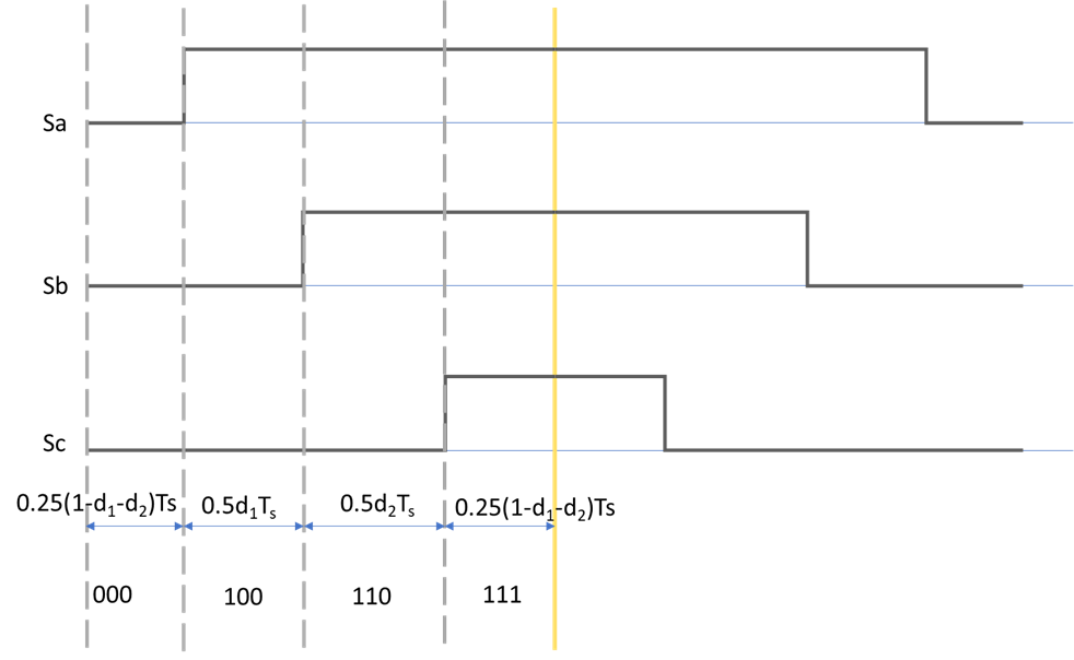
Duty ratios and are the length of the vectors [100] and [111], they are not the direct duty ratios of PWM signals. From the waveform figure, we can obtain the relation between the vector duty ratios and the duty ratio of each PWM signals:
The duty ratio of phase a PWM is:

Similarly, for phase b and c


The same process can be carried out to obtain the duty ratio of all six regions in the hexagon, which is covered in many materials.
Carrier-Based PWM Generation with Zero-Sequence-Injection
to be continued